
News & Articles

VARNISH: The Reliability Threat Hiding Between Samples (Part 1 of 3)
Article by William Gillette (LogiLube, LLC)
A hydraulic or turbine-oil system does not need to suffer a dramatic failure to begin losing performance. Sometimes the first warning is a valve that responds slightly too slowly, an unexplained increase in oil temperature or a filter that does not last as long as it once did.
A paper machine can be running at full production when a hydraulic valve begins responding a fraction of a second too slowly. A gas turbine may be technically available, yet hesitate during a critical start because a servo valve does not move freely. A hydraulic excavator can develop sluggish controls, elevated oil temperature and shortened filter life without producing a single obvious alarm.
In each case, the visible symptom may appear mechanical, electrical or operational. The underlying problem may be varnish or deposits in the lubricant. Varnish cannot be compared to dirt entering the machine. It develops as the hydraulic fluid or turbine oil is subjected to heat, oxygen, pressure, aeration, electrostatic stress and repeated operating cycles. Antioxidants are gradually consumed, and oil-degradation products begin accumulating.
Some of these degradation products remain dissolved in the oil. Others circulate as soft, submicron contaminants. As the fluid passes through cooler areas, narrow clearances and low-flow regions, some of the material can leave solution and deposit on servo-valve spools, bearing surfaces, reservoir walls, heat exchangers and other internal components.

The result is a reliability threat that can remain largely invisible until the machine begins to feel its effects.
A problem that rarely announces itself directly
Varnish does not always produce a clear alarm. Instead, maintenance teams may see recurring valve replacements, unexplained temperature increases, shortened filter life, unstable actuator response, difficult turbine starts or repeated oil changes. A paper machine may experience an intermittent hydraulic-control problem. A blast-hole drill may develop inconsistent feed or rotation control. A haul truck may require hydraulic troubleshooting far from the maintenance shop.
The organization treats the visible symptom, but the fluid continues generating the conditions that caused it.
Modern machinery can intensify the risk. Higher power density, smaller reservoirs, faster fluid turnover, tighter component clearances and higher operating temperatures place increasing stress on the oil. Even when viscosity and particle count remain within broad operating limits, the fluid’s antioxidant reserve may be depleting and deposit forming degradation products may start accumulating.
Varnish is therefore not a simple yes-or-no contaminant. It is an evolving chemical condition.
Understanding that condition begins with oil analysis.
The traditional manual sampling workflow
Most varnish-monitoring programs are built around scheduled manual sampling. The process is familiar as shown in figure 2:
-
A sample is scheduled according to a calendar interval, operating hours or a preventive-maintenance route.
-
A technician travels to the machine, confirms the asset and identifies the designated sampling point.
-
The machine must be operating or placed in an approved operating condition that provides a representative circulating sample.
-
The technician cleans the sampling area, flushes the valve, hose or dead-leg volume, and fills a clean sample bottle.
-
The bottle is capped, labeled and entered into the site’s oil-analysis or maintenance-management system.
-
The sample is packaged and transported to an onsite or offsite laboratory.
-
The laboratory prepares the sample, performs the requested tests and reports the results.
-
A reliability engineer or maintenance specialist reviews the report, compares it
with previous samples and decides whether corrective action is required.
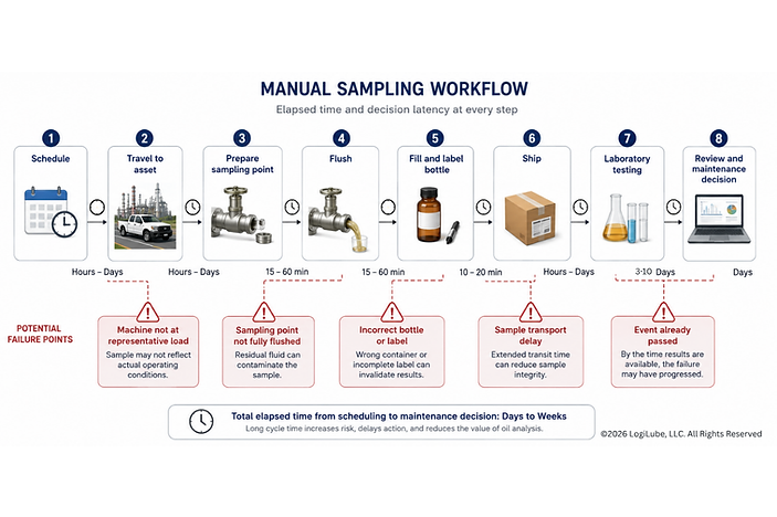
ASTM D4057 provides guidance on manual sampling equipment, container preparation and procedures intended to obtain a representative sample of petroleum products. For turbine systems, ASTM D4378 addresses in-service monitoring programs, including sampling and testing schedules, while emphasizing that operating workload, oil-circuit design, makeup oil and equipment type must be considered when interpreting results.
When properly executed, this workflow provides essential laboratory evidence. Manual sampling is not the problem.
The limitation is that the workflow only observes the fluid at isolated moments.
The sampling blind spot
A scheduled oil sample is a snapshot at that time of operation. The machine, however, operates continuously.
Between two manual samples, the system may experience a high-temperature event, a cooler malfunction, a difficult startup, severe hydraulic loading, water ingress, electrostatic discharge or another condition that accelerates oil degradation.
The event may last several hours or several days and then disappear before the next technician arrives.
.jpg)
The sample collected later may still show some residual effect, but it may not reveal the complete severity, timing or operating context of the event. The laboratory sees the bottle. It does not automatically see what the machine was doing when the degradation occurred.
This interval between scheduled samples is the sampling blind spot. It has several dimensions.
1. The temporal blind spot
A varnish-producing event can begin and end between sampling dates. A monthly or quarterly sample may not capture the fluid while the event is active.
2. The operating-condition blind spot
A sample collected at light load, after an idle period or at a different fluid temperature may not represent the condition that existed during peak production or a turbine-start sequence.
3. The location blind spot
A reservoir sample, drain sample or stagnant sampling tube may not represent the fluid moving through the most thermally stressed or varnish-sensitive area of the system.
4. The decision-delay blind spot
Even a representative sample must be shipped, tested, reviewed and converted into a maintenance decision. By the time action is authorized, the machine may have accumulated additional operating hours under the abnormal condition.
The sampling blind spot does not mean laboratory testing is ineffective. It means laboratory testing needs a better trigger and more operating context.
What ASTM testing tells us about varnish risk
No single laboratory test describes the complete varnish condition of an oil. A strong monitoring program combines several tests that examine different stages of fluid degradation.

RULER® analysis adds another important dimension to varnish monitoring by measuring the remaining antioxidant chemistry in the lubricant. The technology uses linear sweep voltammetry and is reflected in ASTM methods including D6810, D6971, D7527 and D7590, which address antioxidant measurement and depletion trending in different lubricant formulations.
Jo Ameye (Fluitec) contributed to the development and industry standardization of RULER-based testing. When combined with ASTM D7843 Membrane Patch Colorimetry of which Greg Livingstone (Fluitec) was a contributor, RULER helps distinguish between two related conditions: the accumulation of insoluble, deposit forming degradation products and the loss of the antioxidant protection intended to prevent their formation. Neither result should be interpreted alone; the greatest value comes from trending both measurements alongside viscosity, acid number, temperature history and other fluid-condition data.
ASTM D7843: Membrane Patch Colorimetry
ASTM D7843 is the principal standardized method associated with varnish-potential trending in in-service turbine oils.
The test extracts insoluble contaminants from the oil onto a membrane patch. A spectrophotometer measures the color of the patch and reports the result as a CIELAB ΔE value. ASTM describes the method as a guide to the formation of lubricant-generated insoluble deposits and specifies that it should be used as a condition monitoring trend within a broader oil-analysis program. The current standard is ASTM D7843-25e1. It is not intended for turbine oils containing dyes.
MPC is valuable because very small quantities of dark, soft degradation material can produce a meaningful color response even when conventional particle counting does not fully characterize the condition.
However, MPC does not measure all dissolved degradation products, and one test result should not be treated as a universal condemnation limit. The trend, sample handling, operating condition and fluid formulation all matter.
ASTM D7843: Membrane Patch Colorimetry
Antioxidants help protect the base oil from thermal and oxidative degradation. As these additives are consumed, the fluid becomes less capable of resisting oxidation and varnish formation.
ASTM D6971 uses linear sweep voltammetry to measure remaining hindered phenolic and aromatic amine antioxidants in applicable non-zinc turbine oils. ASTM D6810 addresses hindered phenolic antioxidants in non-zinc turbine oils. These tests are commonly associated with RULER-type antioxidant analysis.
ASTM cautions that linear sweep voltammetry does not measure every chemical species contributing to the oil’s remaining useful life or its total oxidative stability. ASTM D7590 therefore emphasizes trending antioxidant depletion relative to a suitable baseline rather than relying only on an isolated absolute result.
Antioxidant testing tells the maintenance team something different from MPC:
-
MPC helps indicate the presence of insoluble deposit-forming material.
-
Voltammetry helps indicate how much of the original antioxidant protection remains.
A fluid can have declining antioxidant reserves before MPC rises sharply. Conversely, an oil can contain varnish-producing material even when some antioxidant reserve remains.
ASTM D2272: Oxidation stability
ASTM D2272, commonly known as RPVOT, evaluates the oxidation stability of steam turbine oils using a rotating pressure vessel. The result is often compared with the new oil baseline to understand how much oxidation resistance remains.
RPVOT is not a direct measurement of varnish deposits. It provides additional evidence about the fluid’s ability to resist further oxidation. This result is given in minutes which is not as easy to correlate to the machine’s operation. Additionally, the RPVOT is not a repeatable test as results of the same oil can vary.
ASTM D2272: Oxidation stability
Other ASTM methods help complete the picture:
-
ASTM D664 measures acid number, which can support trending of acidic oxidation products (which usually occurs after oxidation has occurred).
-
ASTM E2412 provides for trend analysis of in-service lubricants using FTIR spectroscopy and can support monitoring of general degradation patterns.
-
ASTM D445 measures kinematic viscosity, helping confirm whether the oil remains within its required viscosity range.
Water, particulate contamination, air release, demulsibility and elemental analysis may also be important depending on the machine and oil formulation.
The key lesson is that varnish risk is best understood through multiple trends, not a single test or alarm.
Closing the blind spot
SmartOil G3™ Adaptive Dosing is designed to connect continuous machine monitoring with laboratory-grade fluid analysis.
A machine-mounted SmartOil G3 system continuously observes selected fluid properties and associates those measurements with oil temperature, operating hours, load and other machine conditions. The G3 Edge-AI BrainTM establishes a normal operating signature for the individual reservoir and identifies meaningful departures from that baseline.
.png)
The purpose is not to replace ASTM laboratory testing.
It is to determine when laboratory testing is most urgently needed.
When an unusual degradation pattern is detected, SmartOil G3 Exception Sampling™ can collect a representative sample while the machine is operating and the abnormal condition is occurring. The sample can then be analyzed using the appropriate ASTM methods and correlated with the sensor and operating data that triggered its collection.
Instead of receiving only a bottle, asset number and sampling date, the analyst gains a time-aligned record of the event.
That closes much of the traditional sampling blind spot.
From detection to controlled intervention
Once varnish risk has been confirmed, the G3 DOSE™ module can deliver controlled micro-doses of the appropriate varnish control additive formulation.
The objective is not simply to inject an additive. It is to maintain the hydraulic fluid or turbine oil inside an approved operating envelope.
The dosing decision can consider:
-
Varnish-potential trend
-
Antioxidant depletion
-
Viscosity and dielectric behavior
-
Temperature and load history
-
Water and particulate condition
-
Reservoir volume and oil makeup
-
Previous treatment quantity
-
Post-dose fluid response
A bounded dose is delivered, the fluid is allowed to circulate, and the system evaluates the response before any additional treatment is authorized.
This creates a fundamentally different varnish-control model:
Observe continuously
Sample when the condition matters
Confirm through laboratory analysis
Dose precisely
Verify the result
Varnish will not always be visible before it affects machine performance. But the conditions that create varnish often leave measurable signals.
The challenge is capturing those signals before they disappear into the space between scheduled samples.
In Part 2, we examine how SmartOil G3™ turns multiple fluid and machine signals into a defensible dosing decision, and why the quality of that decision matters more than the number of sensors installed.
SmartOil G3™ technology is protected by U.S. Patent No. 10,466,152; 11,761,946; 12,681,003; International Patents, and other U.S. and International Patents Pending
Copyright ©2026 LogiLube, LLC